ELECTRICAL POWER QUALITY REPORTING | EN 50160


EN50160:2010 Report
Summary
The EN50160:2010 Report shows an analysis of the compliance of selected sources based on the EN50160:2010 power quality standard.
Use this report for an analysis and compliance assessment of your
facility against the EN50160: 2010 power quality standard.
Details
EN50160: 2010 is a set of power quality
standards used by certain energy suppliers and energy consumers.
The EN50160: 2010 report uses the following
measurements of the supply voltage:
- Supply
voltage dips
- Temporary
overvoltage
- Supply
voltage unbalance
- Harmonic
voltage
- Interharmonic
voltage
- Power Frequency
- Voltage
magnitude
- Rapid voltage changes (and Flicker)
- Short-
and
- long-term interruptions

Use
the EN50160: 2010 report template to create a report containing comprehensive
analysis of all EN50160: 2010 compliance data logged by multiple meters.
The
compliance summary is based on the EN50160: 2010 limits for each observation
period: each default EN50160 measurement
indicates a pass or did not pass on the compliance test with a Y (yes) or N
(no) respectively.
 |
| VIDEO ON POWER ADVISOR |
Unbalanced voltage causes
All
electrical networks suffer from power quality issues in varying degrees and
frequencies.
Brief sags
and surges are common but networks can exhibit voltage supply irregularities
that may be present for prolonged periods of time, or are constantly present on
the network. Where a voltage imbalance
exists on a supply network, it is usually due to generation faults, unmatched
impedance on transformer banks, or large single phase loads on the three phase
network.
Customer
installation produced voltage imbalances are
most commonly the result of single phase loads not connected evenly across
the 3 phase system. Single phase motors, heating and cooling loads are very
commonly connected in such a manner that one phase conductor carries
significantly more current than the other two.
The
Line to Neutral Voltage of one phase is lower than the other two.
Similarly,
where the majority of the load is connected over only two phases, one Line to
Neutral voltage is higher than the other two. In either case, Line to Line
voltages are affected.
Figure 1 demonstrates an over voltage on one line, and
an under voltage on another at the Medium Voltage (MV) or High Voltage (HV)
transformer, while the third is at specified voltage.

On the Low Voltage (LV) secondary, not only are the
Line to Neutral voltages on two phases clearly over and under by 10%
respectively, measuring the Line to Line vectors (dashed lines) shows voltage
varying from specification.
Further reading is available in other
papers referencing phase angle shift that occurs with unbalanced voltage in
three phase installations.
Unbalanced voltage and induction motors
The effect of unbalanced voltage on induction motors is widely known by most technicians and plant engineers.
Motor torque and speed are negatively affected and the motor may produce excessive noise.
The voltage imbalance can
also cause an increase in current imbalance and a temperature rise far greater
than the voltage imbalance percentage.
We can calculate the increased
temperature in an induction motor winding as a result of voltage imbalance.
Voltage imbalance in a 3 phase system is expressed as a single
percentage.
As in Figure 1, there may exist an under voltage and an over voltage.
To calculate the system imbalance and the resulting temperature rise in
the winding, the following formulae are used:

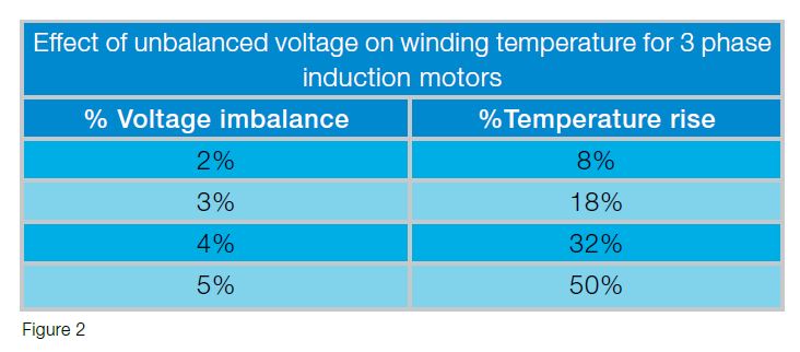
The table in Figure 2 demonstrates the formula above outlining the
exponential winding temperature increase compared with the increase in voltage
imbalance.
An imbalance greater than 2% is unacceptable, as it results in a
temperature rise in the winding that will be beyond the motors specification;
the life of the motor may be decreased. NEMA
limits require no more than 5% unbalanced voltage.

Studies show that the usefull life of the motor halves (!) with every 10% of the mormal insulating material working temperature
increase.
Three phase induction motors should be de-rated according to the chart below.

Not only does the
increased operating heat induce premature expiration of the motor, excess
current is also drawn with no additional power output, therefore over-stressing
the supply cables and potentially reaching levels where the current overloads
and the Variable Speed Drives (VSD) over current protection will trip.
VSD diodes, DC link capacitors and rectifier power supplies will experience additional thermal stress as a result of the increased AC line currents-to compensate for the voltage imbalance.
Triple harmonics can also be produced as a result of the increased stress to the rectifier diodes.


 |
| ELECTRICAL THEORY OF GRIDS |


Σχόλια
Δημοσίευση σχολίου